Dell Inspiron 4100
 |
NOTICE: Only a certified service technician should perform repairs on your computer. Damage due to servicing that is not authorized by Dell is not covered by your warranty. |
|
NOTICE: To avoid damaging the computer, perform the following steps before you begin working inside the computer. |
 |
HINT: Make sure the computer is turned off and not in suspend mode or hibernate mode. If you cannot shut down the computer using the computer operating system, press and hold the power button for 4 seconds. |
|
NOTICE: To avoid damaging the system board, you must remove the main battery and secondary battery (if present) before you service the computer. |
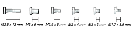
The procedures in this manual require the following tools:
|
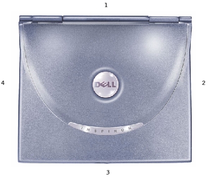
1 |
back |
|
2 |
right |
|
3 |
front |
|
4 |
left |
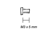
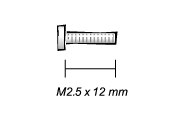
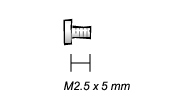
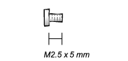
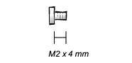
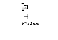
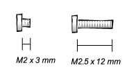
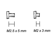
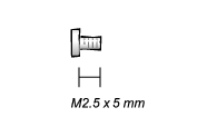
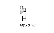
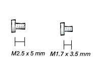
When you are removing and replacing components, photocopy the placemat as a tool to lay out and keep track of the screws. The placemat provides the number of screws and their sizes.
|
NOTICE: When reinstalling a screw, you must use a screw of the correct diameter and length. Make sure that the screw is properly aligned with its corresponding hole, and avoid over tightening. |
|
NOTICE: Only a certified service technician should perform repairs on your computer. Damage due to servicing that is not authorized by Dell is not covered by your warranty. |
|
NOTICE: Unless otherwise noted, each procedure in this manual assumes that a part can be replaced by performing the removal procedure in reverse order. |
|
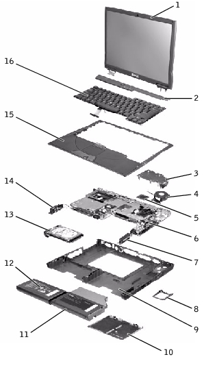
1 |
top cover display assembly |
9 |
bottom case assembly |
|
2 |
center control cover |
10 |
memory module cover |
|
3 |
thermal cooling assembly |
11 |
module bay device |
|
4 |
hybrid cooling fan |
12 |
main battery |
|
5 |
microprocessor module |
13 |
hard drive |
|
6 |
system board |
14 |
left speaker/antenna assembly |
|
7 |
right speaker/antenna assembly |
15 |
palm rest assembly |
|
8 |
fan guard |
16 |
keyboard |
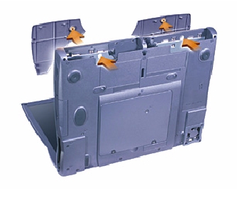
Repeat the process on each side.
|
NOTICE: Disconnect the computer and any attached devices from electrical outlets, and remove any installed batteries. |
|
NOTICE: The hard drive is very sensitive to shock. Handle the hard drive by its edges (do not squeeze the top of the hard drive case), and avoid dropping it. |
|
NOTICE: Read "Preparing to Work Inside the Computer" before performing the following procedure. |
|
NOTICE: To prevent data loss, turn off your computer before removing the hard drive. Do not remove the hard drive while the computer is running, in standby mode, or in hibernate mode. |
 |
CAUTION: If you remove the hard drive from the computer when the drive is hot, do not touch the metal housing of the hard drive. |
|
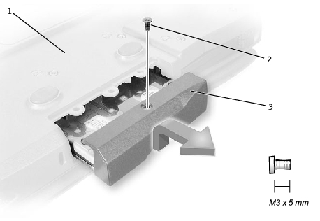
1 |
bottom of computer |
|
2 |
M3 x 5-mm screw |
|
3 |
hard drive door |
|
NOTICE: Use firm and even pressure to slide the hard drive into place. If you force the hard drive into place using excessive force, you may damage the connector. |
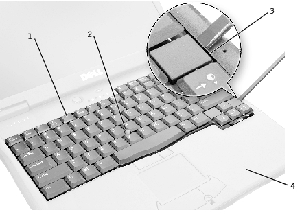
If you ordered the optional modem at the same time that you ordered your computer, Dell has already installed the modem for you.
|
1 |
pull-tab |
|
2 |
modem cable connector |
|
3 |
modem cable |
|
NOTICE: The cable connectors are keyed for correct insertion; do not force the connections. |
|
NOTICE: To prevent damage to devices, place them in a travel case when they are not inserted in the computer. Store devices in a dry, safe place, and avoid pressing down on them or placing heavy objects on top of them. |
|
NOTICE: Disconnect the computer and any attached devices from electrical outlets, and remove any installed batteries. |
|
NOTICE: To avoid ESD, ground yourself by using a wrist grounding strap or by touching an unpainted metal surface on the computer. |
|
NOTICE: Read "Preparing to Work Inside the Computer" before performing the following procedure. |
|
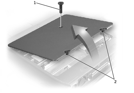
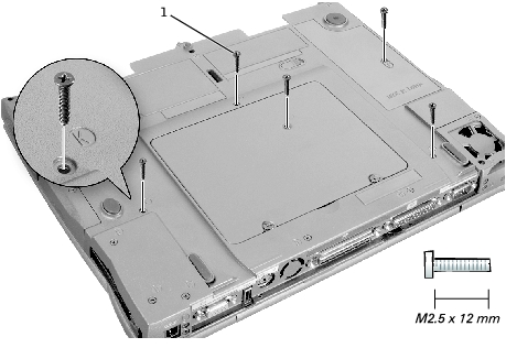
1 |
M2.5 x 12-mm screw (1) |
|
2 |
captive screws (2) |
|
NOTICE: Disconnect the computer and any attached devices from electrical outlets, and remove any installed batteries. |
|
NOTICE: To avoid ESD, ground yourself by using a wrist grounding strap or by touching an unpainted metal surface on the computer. |
|
NOTICE: Read "Preparing to Work Inside the Computer" before performing the following procedure. |
|
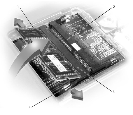
NOTICE: To prevent damage to the memory module connector, do not use tools to spread the inner metal tabs that secure the memory module. |
The module should pop up.
|
1 |
JDIM 1 |
|
2 |
JDIM 2 |
|
3 |
memory module sockets (2) |
|
4 |
inner tabs (2 per socket) |
|
HINT: Memory modules are keyed, or designed to fit into their sockets, in only one direction. |
|
NOTICE: The memory module must be inserted at a 45-degree angle to avoid damaging the connector. |
You must remove the Mini PCI card before the system board can be removed.
|
NOTICE: Disconnect the computer and any attached devices from electrical outlets, and remove any installed batteries. |
|
NOTICE: To avoid ESD, ground yourself by using a wrist grounding strap or by touching an unpainted metal surface on the computer. |
|
NOTICE: Read "Preparing to Work Inside the Computer" before performing the following procedure. |
|
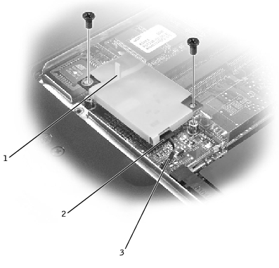
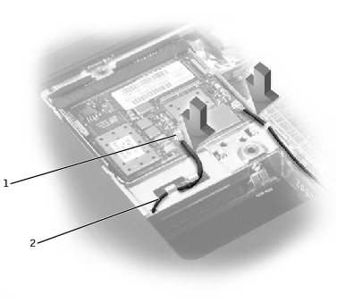
1 |
antenna connectors on card (2) |
|
2 |
antenna cables (2) |
|
NOTICE: The connectors are keyed for correct insertion; do not force the connections. |
|
NOTICE: Disconnect the computer and any attached devices from electrical outlets, and remove any installed batteries. |
|
NOTICE: To avoid ESD, ground yourself by using a wrist grounding strap or by touching an unpainted metal surface on the computer. |
|
NOTICE: Read "Preparing to Work Inside the Computer" before performing the following procedure. |
|
1 |
M2.5 x 12-mm screws (5) |
|
NOTICE: The key caps on the keyboard are fragile, easily dislodged, and time-consuming to replace. Be careful when removing and handling the keyboard. |
|
1 |
keyboard |
|
2 |
track stick |
|
3 |
scalloped edge of blank key |
|
4 |
palm rest |
|
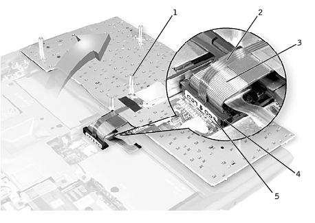
NOTICE: Do not pull on the keyboard flex and track stick cables. |
|
1 |
boss support (5) |
|
2 |
track stick cable |
|
3 |
keyboard flex cable |
|
4 |
keyboard connector |
|
5 |
orientation label |
|
NOTICE: To avoid damage to the connector pins, press the keyboard connector evenly into the interface connector on the system board, and do not reverse the keyboard connector. |
The keyboard connector may have a label on it that shows the correct orientation of the keyboard connector to the system-board interface connector.
|
NOTICE: Position the keyboard flex and track stick cables so that they are not pinched when you replace the keyboard in the bottom case. |
|
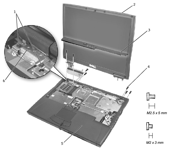
NOTICE: You must remove the display assembly before you remove the palm rest. |
|
NOTICE: Disconnect the computer and any attached devices from electrical outlets, and remove any installed batteries. |
|
NOTICE: To avoid ESD, ground yourself by using a wrist grounding strap or by touching an unpainted metal surface on the computer. |
|
NOTICE: Read "Preparing to Work Inside the Computer" before performing the following procedure. |
|
1 |
M2 x 3-mm screws (4) |
|
2 |
top cover |
|
3 |
center control cover |
|
4 |
M2.5 x 5-mm screws (5) |
|
5 |
bottom case |
|
6 |
EMI shield bracket |
|
NOTICE: When reconnecting the display-feed flex cable connector to the system board, push down on the top left and right ends of the connector. Pressing on the center of the connector may damage resistors and compromise EMI protection in the computer. |
|
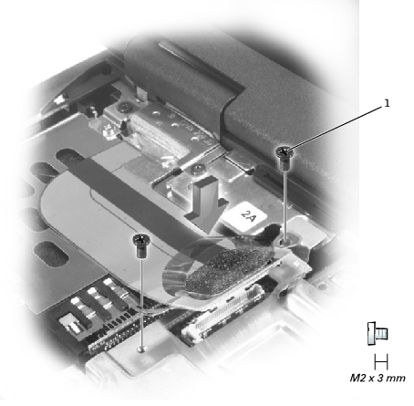
1 |
M2 x 3-mm screws (2) |
|
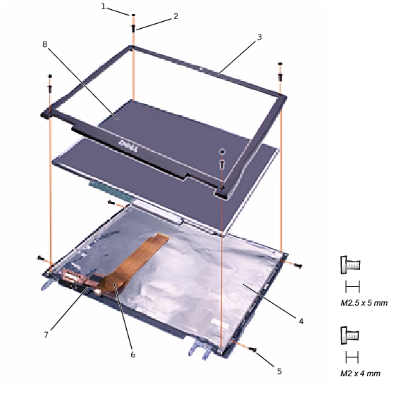
1 |
rubber screw covers (6) |
5 |
M2 x 4-mm screws (5) |
|
2 |
M2.5 x 5-mm screws (4) |
6 |
display-feed flex cable |
|
3 |
display bezel |
7 |
flex-cable retention bracket |
|
4 |
top cover |
8 |
display panel |
|
NOTICE: Disconnect the computer and any attached devices from electrical outlets, and remove any installed batteries. |
|
NOTICE: To avoid ESD, ground yourself by using a wrist grounding strap or by touching an unpainted metal surface on the computer. |
|
NOTICE: Read "Preparing to Work Inside the Computer" before performing the following procedure. |
|
NOTICE: Carefully separate the bezel from the top cover to avoid damage to the bezel. |
|
NOTICE: Disconnect the computer and any attached devices from electrical outlets, and remove any installed batteries. |
|
NOTICE: To avoid ESD, ground yourself by using a wrist grounding strap or by touching an unpainted metal surface on the computer. |
|
NOTICE: Read "Preparing to Work Inside the Computer" before performing the following procedure. |
|
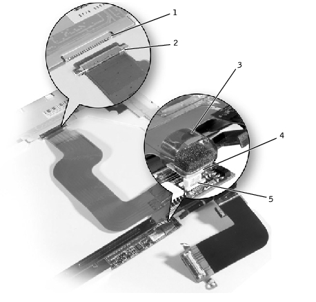
HINT: If you have a Hitachi display panel, remove the two M2 x 4- mm screws from the center of the left side of the display panel. |
|
1 |
display panel connector |
|
2 |
top flex-cable connector |
|
3 |
pull tab |
|
4 |
bottom flex cable connector |
|
5 |
inverter connector |
Reinstall the five M2 x 4-mm screws that secure the display panel to the top cover.
|
NOTICE: Disconnect the computer and any attached devices from electrical outlets, and remove any installed batteries. |
|
NOTICE: To avoid ESD, ground yourself by using a wrist grounding strap or by touching an unpainted metal surface on the computer. |
|
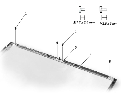
1 |
M1.7 x 3.5-mm screws (2) |
|
2 |
M2.5 x 5-mm screws (2) |
|
3 |
display latch |
|
4 |
bracket |
On 14.1-inch SXGA+ and UXGA panels, align the screw holes and place the display latch and attached bracket in the top cover.
|
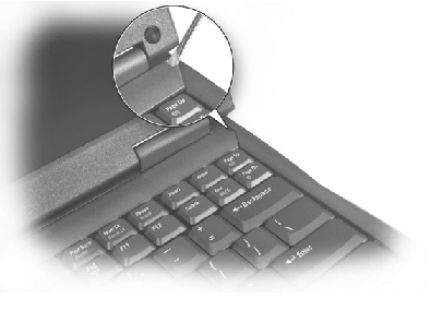
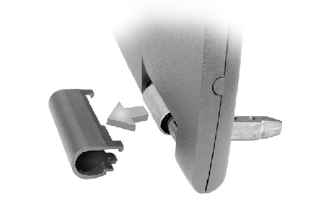
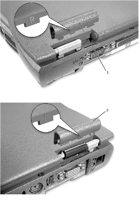
HINT: The right plastic hinge cover label includes an "R," and the left plastic hinge cover label includes an "L." The hinge cover labels face the back of the computer. |
|
1 |
right hinge cover |
|
2 |
left hinge cover |
|
NOTICE: Disconnect the computer and any attached devices from electrical outlets, and remove any installed batteries. |
|
NOTICE: To avoid ESD, ground yourself by using a wrist grounding strap or by touching an unpainted metal surface on the computer. |
|
NOTICE: Read "Preparing to Work Inside the Computer" before performing the following procedure. |
|
NOTICE: You must remove the display assembly before you remove the palm rest; the display hinges pass through the back of the palm rest. |
|
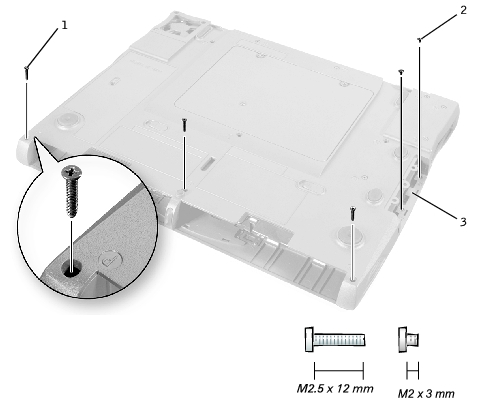
1 |
M2.5 x 12-mm screws (3) |
|
2 |
M2 x 3-mm screws (2) |
|
3 |
hard-drive bay door |
|
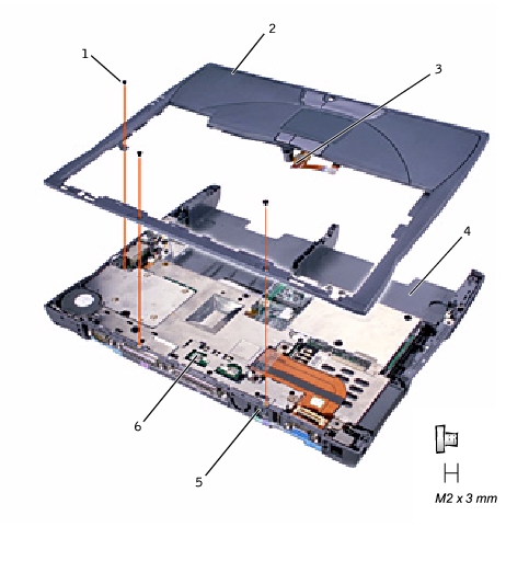
1 |
M2 x 3-mm screws (3) |
|
2 |
palm rest |
|
3 |
palm-rest flex cable |
|
4 |
bottom case |
|
5 |
back center of the palm rest |
|
6 |
touch pad connector |
|
NOTICE: Carefully separate the palm rest from the bottom case to avoid damage to the palm rest. |
|
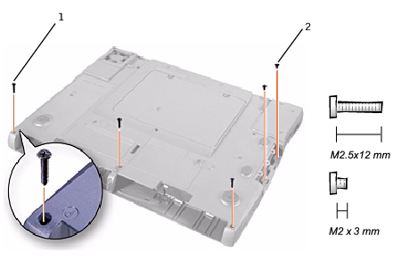
1 |
M2.5 x 12-mm screws (3) |
|
2 |
M2 x 3-mm screws (2) |
|
NOTICE: Disconnect the computer and any attached devices from electrical outlets, and remove any installed batteries. |
|
NOTICE: To avoid ESD, ground yourself by using a wrist grounding strap or by touching an unpainted metal surface on the computer. |
|
NOTICE: Read "Preparing to Work Inside the Computer" before performing the following procedure. |
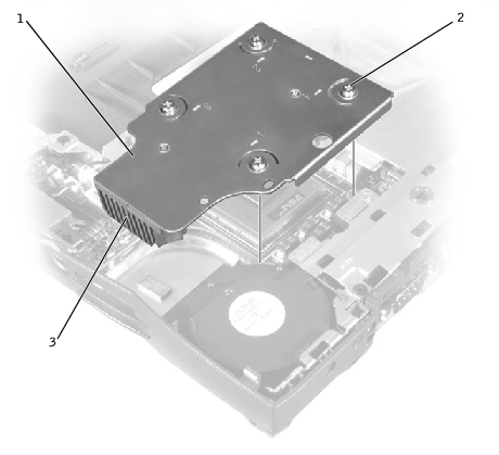
|
1 |
microprocessor thermal cooling assembly |
|
2 |
captive screws (4) |
|
3 |
right side |
|
NOTICE: Disconnect the computer and any attached devices from electrical outlets, and remove any installed batteries. |
|
NOTICE: To avoid ESD, ground yourself by using a wrist grounding strap or by touching an unpainted metal surface on the computer. |
|
NOTICE: Read "Preparing to Work Inside the Computer" before performing the following procedure. |
|
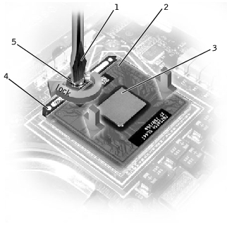
NOTICE: Do not touch the processor die. Press and hold the microprocessor down on the substrate on which the die is mounted while turning the cam screw to prevent intermittent contact between the cam screw and microprocessor. |
|
NOTICE: To avoid damage to the microprocessor, hold the screwdriver so that it is perpendicular to the microprocessor when turning the cam screw. |
|
1 |
screwdriver (perpendicular to microprocessor) |
|
2 |
pin-1 corner |
|
3 |
processor die (do not touch) |
|
4 |
ZIF socket |
|
5 |
ZIF-socket cam screw |
|
NOTICE: To ensure maximum cooling for the microprocessor, do not touch the heat transfer areas on the microprocessor thermal cooling assembly. The oils in your skin reduce the heat transfer capability of the thermal pads. |
|
NOTICE: When removing the microprocessor module, pull the module straight up. Be careful not to bend the pins on the microprocessor module. |
The ZIF-socket cam screw secures the microprocessor to the system board. Take note of the arrow on the ZIF-socket cam screw.
|
NOTICE: Ensure that the cam lock is in the fully open position before seating the microprocessor module. Seating the microprocessor module properly in the ZIF socket does not require force. |
|
NOTICE: A microprocessor module that is not properly seated can result in an intermittent connection, or permanent damage to the microprocessor and ZIF socket. |
|
HINT: The pin-1 corner of the microprocessor module has a triangle that aligns with the triangle on the pin-1 corner of the ZIF socket. |
|
NOTICE: You must position the microprocessor module correctly in the ZIF socket to avoid permanent damage to the module and the socket. |
When the microprocessor module is correctly seated, all four corners are aligned at the same height. If one or more corners of the module are higher than the others, the module is not seated correctly.
|
NOTICE: Hold the microprocessor down while turning the cam screw to prevent intermittent contact between the cam screw and microprocessor (see "Removing the Microprocessor Module"). |
To update the BIOS:
System hardware failures: #0010
Strike the F1 key to shutdown
Failure override
Processor update failure. Reload current BIOS
Strike the F1 key to continue, F2 to run the setup utility.
|
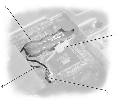
NOTICE: The reserve battery provides power to the computer's RTC and NVRAM when the computer is turned off. Removing the battery causes the computer to lose the date and time information as well as all user-specified parameters in the BIOS. If possible, make a copy of this information before you remove the reserve battery. |
|
NOTICE: Disconnect the computer and any attached devices from electrical outlets, and remove any installed batteries. |
|
NOTICE: To avoid ESD, ground yourself by using a wrist grounding strap or by touching an unpainted metal surface on the computer. |
|
NOTICE: Read "Preparing to Work Inside the Computer" before performing the following procedure. |
|
1 |
reserve battery |
|
2 |
speaker connector |
|
3 |
system board connector |
|
4 |
reserve battery cable |
|
NOTICE: Disconnect the computer and any attached devices from electrical outlets, and remove any installed batteries. |
|
NOTICE: To avoid ESD, ground yourself by using a wrist grounding strap or by touching an unpainted metal surface on the computer. |
|
NOTICE: Read "Preparing to Work Inside the Computer" before performing the following procedure. |
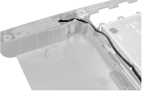
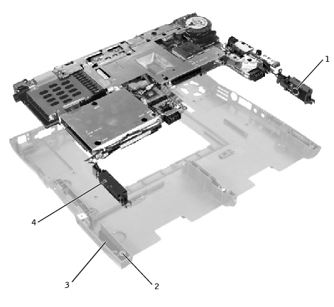
The speakers are located on the front left and right sides of the bottom case. Each speaker assembly is marked with a left or right label. Take note of the speaker and antenna wire routing so that you can replace them properly under their routing clips.
|
1 |
right speaker |
|
2 |
palm-rest screw post |
|
3 |
bottom case holders (2) |
|
4 |
left speaker |
|
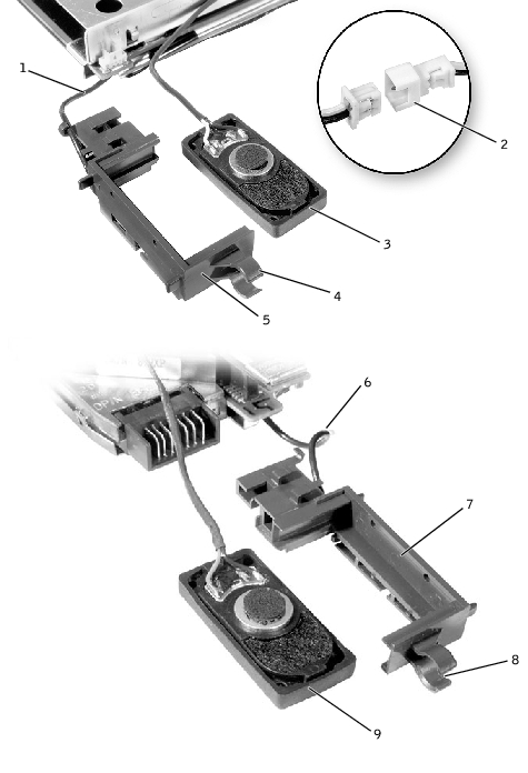
1 |
antenna cable |
6 |
antenna cable |
|
2 |
in-line connector |
7 |
right speaker holder |
|
3 |
left speaker |
8 |
mounting ring |
|
4 |
mounting ring |
9 |
right speaker |
|
5 |
left speaker holder |
|
|
|
NOTICE: Do not pull the antenna wire when removing the speaker. |
|
NOTICE: Handle the speaker assemblies and speakers with care to avoid damaging the speaker cones. |
|
HINT: The left speaker has an in-line connector, and its antenna cable is longer than the antenna cable of the right speaker. |
|
NOTICE: Make sure the speaker wires are under their routing clips. Route the left speaker wire properly between the battery bay and hard drive area. |
|
HINT: Speakers face out in the bottom case holders. |
The system board's BIOS chip contains the service tag sequence, which is also visible on a barcode label on the bottom of the computer. The replacement kit for the system board includes a CD that provides a utility for transferring the service tag sequence to the replacement system board.
|
NOTICE: Disconnect the computer and any attached devices from electrical outlets, and remove any installed batteries. |
|
NOTICE: To avoid ESD, ground yourself by using a wrist grounding strap or by touching an unpainted metal surface on the computer. |
|
NOTICE: Read "Preparing to Work Inside the Computer" before performing the following procedure. |
|
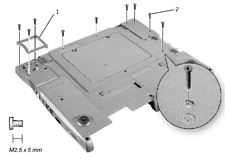
1 |
fan guard |
|
2 |
M2.5 x 5-mm screws (9) |
|
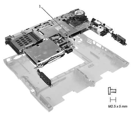
1 |
M2.5 x. 5-mm screw (1) |
|
HINT: Be sure to route cables so that they will not be crimped or pinched when the complete assembly is put back together. |
|
HINT: After replacing the system board, be sure to enter the computer service tag sequence into the BIOS of the replacement system board. |
|
NOTICE: Disconnect the computer and any attached devices from electrical outlets, and remove any installed batteries. |
|
NOTICE: To avoid ESD, ground yourself by using a wrist grounding strap or by touching an unpainted metal surface on the computer. |
|
NOTICE: Read "Preparing to Work Inside the Computer" before performing the following procedure. |
To prevent the latch assembly from coming loose, apply pressure to the latch and spring while removing the latch button. If the latch assembly does come loose from the case:
|
HINT: The latch will not function properly if the slider is oriented incorrectly. |
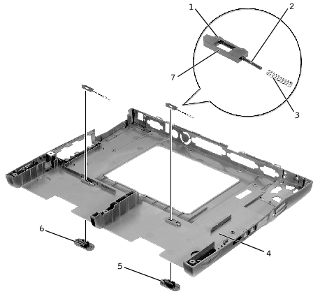
|
1 |
bumps (2 per latch) |
5 |
latch buttons (2) |
|
2 |
slider |
6 |
snap tabs (2 per latch button) |
|
3 |
spring |
7 |
wear rib |
|
4 |
bottom case |
|
|
To prevent the latch assembly from coming loose, apply pressure to the latch and spring while replacing the latch button.